Tuesday, December 2, 2014

INFR3110 Blog 5


With exams coming up, I will be devoting this blog to briefly review and refresh a few topics learned earlier this course.

To begin, one of the new concepts is the idea of a smart pointer. Essential a smart pointer is a special object that contains a pointer along with the additional of potential data members and functions. A smart pointer is able to do what a regular pointer cannot natively. An example of this is storing a reference count to ensure that there are no dangling pointers with zero references, causing a potential memory leak.  A smart pointer will intelligently know to destroy itself if the situation ever arises.  This is just one of the examples of a smart pointer, for instance a weak pointer will still contain some additional functions but will not automatically destroy itself if reference count reaches zero. The major disadvantage with a smart pointer is based around implementation. It is very difficult to implement a good smart pointer. Thankfully it is already implemented in 2loc.

Moving away from the traditional object orient design that we have all been familiar with, we look to a new concept of entity component systems. In the entity component system, each element of entity, component and system serve unique purposes.

The entity itself is nothing more of a container for data and its unique id. An entity has multiple components attached to it. It is important to remember that the components and the entity are just data. A good example to think about this, especially if you have used unity is that each object has sub-components that are added to it. These objects or data can be for instance components that describe the object - a material with data such as the diffuse, normal, specular maps ; a bounding box, with a vector for each pointer or perhaps a radius; a transformation, perhaps divided into rotation, position, scale; a mesh describing the objects; containing arrays of vertex data. Each of these components are attached to the entity and make up the entity, these components are attachable and detachable - the entity itself does not matter what or how many components are attached.  The most important aspect of the entity in this case is being modular.

When it comes to functionality, it is up to the systems to perform the task given an entity. In order for a given system to perform its function on an entity, the entity must have the required components attached; again it does not matter if the entity has more components than the system needs. If the entity indicated above were to be fed to say a render system, the relevant components – the mesh and the material and perhaps the transformation components will be used by the system to perform the operation of rendering. If the same entity were to be passed to physics system, than the relevant components would be transformation and bounding box components. This is just a trivial example of how the entity component system works. The systems themselves do not store data but access it through entities and uses it to perform calculations. These systems operate sequentially – you can have for example an AI system to determine an entity’s movement than have a physics system go and compute afterwards.

To further illustrate the entity component system using an example. Take for instance a generic entity with no components attached to it other than its name (id). To make this entity do something we can attach a transformation component to it. Now we can move it around the world, however there will likely be almost no systems that will be able to use it. If we were to add a light component to it – for instance a component that can make the entity a light source, describing its light color, range, attenuation and direction. The system can thus perform appropriate calculations using this entity to light other entities.

Byte56. (2012, July 2). Role of systems in entity systems architecture. [Reply Post]. Retrieved from http://gamedev.stackexchange.com/questions/31473/role-of-systems-in-entity-systems-architecture


Gregory, J. (2009). Runtime Gameplay Foundation Systems.  Game engine architecture. Wellesley, Mass.: A K  Peters

Friday, November 28, 2014

INFR3110 Blog 4


Physics in a game serves many purposes, but its primary goal is to create realism. The addition of physics brings along many emerging dynamics; from complex real-world interactions such as gravity, springs, water, clothing movement, to explosions, there is much that a physics engine can do to enhance the overall experience of your game. One vital topic of physics is collision detection.

In order to represent objects in our game world, we typically need a collidable entity – or bounding box, shape to represent it in a “physics world”. The collidable entity is not visible to the player, but is attached and used to represent objects in our game world. Implementation wise, as the entities in our physics world is updated, based of elements such as gravity, and force, the game world will use the updated collidable entity to transform our game world objects. An example of this would be having say a basketball in our game world, and creating than attaching a collidable entity from the physics world. The collidable entity will likely be a sphere shape and will be given physics properties such as bounciness, mass and drag. When our physics world updates, the collidable entity will frame by frame fall to the ground and bounce.  To apply this to our game world, we simple use the updated attributes from the collidable entity and apply them to our game world’s basketball mesh.

Above, we see that we used a sphere primitive to represent our basketball in the physics world, however for more complex shapes there are many other options. The player object, depending on game complexity will likely be represented with a capsule in our physics world.  Another primitive for our collidable entities is the box.

When it comes to actually detecting collision between objects, some of the methods are :

Axis-aligned bounding box (AABB) is one of the simplest implementations of collision detection; it involves creating bounding boxes from the same coordinate system.  Collision is detected if any points are inside another. Essentially for the 2 objects a collision is checked for, it is the equivalent to drawing a box, with the axis x, y, z to be parallel to one another. The major problem with this method is if one of the objects is rotated, in which case the bounding box becomes very inaccurate, with the potential for having a lot of empty space. This was the case for my previous GDW game, where fences had bounding boxes that were too big, when rotated or checked against the character at a non-parallel angle.

The other method that remedies the above problem is to create an Oriented bounding box(OBB), essentially the boxes will no longer have parallel axis, but will be rotated by its local transformation. To detect the actual collision, there are methods such as using Seperating Axis Theorem(SAT).

The basic idea behind the SAT algorithm is to create a projection of each edge, perpendicular to itself (normal). A vector is formed and if, there is no overlap between the projection formed and the project of the other bounding box, this edge will have no collision. If there exists a projection where there is no overlap, than the 2 bounding boxes is determined to be not colliding.

Detection of other primitives is more straightforward. For instance, collision between spheres can be determined by comparing their respective radii to get the distance from one another.

Gregory, J. (2009). Collision and Rigid Body Dynamics. Game engine architecture. Wellesley, Mass.: A K Peters

Friday, November 7, 2014

INFR3110 Blog 3


Barely in the groove of using 2loc, after many attempts, hurdles, scrapping together pieces of information here and there, and even abandoning some projects, I’ve managed to complete a few medium homework questions. 2loc has been a challenging beast to say the least and it is the primary adversary when it comes to completing these assignments. Constantly scratching my head and questioning everything, I’ve bided for time in hopes of learning new details from either the lecture or the tutorials.

One of the more challenging of the completed - Shadow mapping is simple in theory, but the implementation in 2loc involves what I believe to be the combined use of many unknown 2loc features lurking in the depths. The main points to take away in the implementation is the use of ShaderOperators to update the passed in light viewprojection matrix. As I did not properly understand ECS, I had been scratching my head as to why the light camera’s passed back view projection matrix was wrong – I expected it to be computed and then returned but was forgetting that the system was the one to do that, and has yet to perform the task.The other important part is passing in specific uniforms not exposed or directly controlled by the programmer. Rather, these functions were hidden away and must be enabled. Even then, finding the exact name of the uniform was difficult. It would seem that this has been alleviated in the latest distribution, where these functions are exposed in full and would even warn you if they are enabled and not used in the shader; a bit late for me, as much time was lost in finding and learning these features. From then on it was smooth sailing - calculating the position to shadow coord by using the lights’ view projection and the model matrix, than deserializing it to sample from the shadowmap. Following the standard algorithm already taught to us and a bit of tweaking to get rid of shadow acne and voila, shadow mapping.

Shadowmapping in 2loc

The other bit I worked on was Pacman. The most challenging element of this was in figuring out what method to implement the collision. I was tempted to use box2D, but realistically it requires the arduous process of creating static bodies for all the walls. Looking towards the future, I decided on a supposedly easy approach of collision masks. The only problem encountered was the different coordinate systems between sampling the texture with the build in readpixels function. The simplest remedy being to rotate the png itself.

As for the rest of this term and the hard homework questions waiting, the roadmap I had in mind is to take Pacman all the way; a total of 35xp is tantalizing. The obligation of doing the AI centric homework question compels me as I am taking “Artificial intelligence for gaming” this semester. Salvaging my A* algorithm from the previous year, I will be able to implement the AI for the ghosts to a much more accurate degree. If you’ve read up on the AI of the ghosts, it would seem they are a lot more complicated than meets the eye…

Friday, October 17, 2014

INFR3110 Blog 2


Well, not much to say here in terms of development progress. Learning 2LoC has been a much greater challenge than anticipated. The simultaneous requirement of needing to work on both capstone and develop a game specifically for this course is already taking its toll. The early design for the game is still in its infancy, which is to say, behind schedule when contrasted with our peers in GDW.

The first hurdle of homework questions was relatively straightforward. The only engine related question I completed took longer than the other 3 Maya-based combined. I definite sign of things to come… The 2loc engine related question I completed was the per fragment/per vertex lighting shader; simple due to the availability of relevant project samples. An important note, as there are not enough samples to sufficiently complete the homework questions.

The next difficulty set – medium is going to be more challenging. Over the past few days, I have spent hours trying to get shadow mapping working; to no avail. The primary difficulty lies in understanding how to pass a specific matrix transformation to the shader, the engine seems to automatically calculate and pass the MVP directly to the shader using a specific name; the need is to intercept these calculations or to calculate them outside the engine. Learning the functionality of the engine and finding just what hidden and obscure feature that allows me to accomplish a specific task is a real trial. Because of this, I am required to take debugging to a whole new, laborious level – that of having to check the transformation matrices outputted by different functions to compare with hand written calculations. Perhaps someday I will find the hidden view projection matrix function.

The lack of documentation means I have to take and archive every bit of new information about the engine. It would seem that I have to wait, wait until the course catches up to the requirements of some homework questions before proceeding further. Perhaps I was a little too eager in pursuing that which has yet to be discussed. My sources tell me that shaders and integration of external engines like Bullet will be covered in the coming weeks.

Although this course’s setup for homework questions is more generous than that of previous courses, this invisible wall of difficulty in learning 2loc, is obstructing me from putting to use my preceding knowledge.

Thursday, September 25, 2014

INFR3110 Blog 1


With this first blog, I don’t have much to write about. With capstone this semester, development has yet to begin, projects are still being determined.

I recall the amount of effort put into trial and error, working on last year’s GDW game; all the while learning OpenGL. Taking a quick glance at the 2LoC engine, rather than revel in the comfort of familiarity I am instead anxious. Gazing into the foreboding unknown the absence of experience embraces me once more. This is not new to me, in the past, at Seneca College I have worked with a custom game framework/engine made by my professor. I’ve spent the better time of that semester learning the intricacies of everything before finally being able to delve into creation.
Source control is back at long last, there wasn’t any need for it in the past year. The lack of a need for many to work on the same file meant dropbox was sufficient.  In the past, I’ve have used quite a bit of source control in the form of SVN both in the workplace and at Seneca. It’s been quite some time since I’ve last used it. Mercurial appears similar on the surface; using different names for operations of commit/update and the like.

In my previous blogs I wrote about what was covered in class using examples implemented in game, but for now with a lack of progress, I won’t bother with recitation of slides. I assure you that the next blog will surely be content abound.


Sunday, March 30, 2014

Blog 10

In the interest of adding some a quick enhancement to the graphics of our game, I looked through some additional effects

Fog

Fog is the natural phenomenon in which water in the air obscures light, the further away, the more fog obscures the light reaching the viewer. Fog can be useful as a way to hide geometry and create a sense of depth and atmosphere. In old OpenGL fog can be achieved by just enabling it and setting various attributes. It is performed at the end of the pipeline, affecting the final pixels. With the use of shaders, variance and customization is available to create more interesting varieties of fog. To create a fog effect, the distance of a pixel to the camera is taken into account, the further away, the more foggy; this is akin to depth of field. There are many ways to create fog such as by using height or even particles so that the fog can be affected by light and shadow.

A simple implementation:
vec3 fogColour = vec3(0.722, 0.961, 0.949);
float z = gl_FragCoord.z / gl_FragCoord.w;
float density = 0.001;
float fog = exp2(-density * density * z * z);
fog = clamp(fog, 0.0, 1.0);

fragColour.rgb = mix(fogColour, diffuse, fog);

Light fog on distant ocean

For more advanced fog effects, the location of the light source can be taken into account to create regions in which fog is illuminated the closer it is to the light source – blend between the color of the fog and the color of light using the dot product of the light vector and the distance to the pixel (similar to diffuse lighting), do this on top of regular fog calculations.

God Rays, also known as light scattering and crepuscular rays is the effect of rays of light hitting small surfaces such as particles or fog and scattering. The resulting scatter of light creates a visible streak of light. God rays are a post-processing effect. Firstly, a vector is created from the light source to the screen space specific pixel in the fragment shader. This vector is then sampled along with different values of decay and weighing to determine its color.

To continue from last week’s blog, I’ve managed to implement a basic particle system rendered using the geometry shader. The important element on top of using it for smoke, clouds and ash in game is that it serves the purpose of creating in-game messages such as score updates and player instructions.


Quilez, I. (2010). Better Fog. [Web log post] Retrieved from http://www.iquilezles.org/www/articles/fog/fog.htm

Nguyuen, H. (2008). Chapter 13. Volumetric Light Scattering as a Post-Process. CPU Gems 3. Retrieved March 30, 2014, from http://http.developer.nvidia.com/GPUGems3/gpugems3_ch13.html

Sunday, March 23, 2014

Blog 9

Geometry Shader


The geometry shader is a programmable shader located after the vertex shader and before the rasterization stage. Where the vertex shader processes vertices, and the fragment shader fragments/pixels, the geometry shader processes primitives.  Depending on what the input is set to, the geometry shader takes in a single triangle, point, quad, etc… and can perform operations such as removing/adding or even changing them. The geometry shader can output a completely different primitive from the input.

The geometry shader can be used to create particles by receiving a point and outputting a quad representing the sprite of the particle. With this, all that is needed are the locations of where each particle should be located.

Another use for the geometry shader is for tessellation – increasing the number of polygons thereby making the model more detailed. With tessellation, a low-poly model can be loaded and altered into a high-poly model using just the geometry shader; saving on the costly overheads of complex models. With OpenGL 4, this can be done using the new shaders – the tessellation control shader and the tessellation evaluation shader.


Development Progress


It’s been a while since I gave an update on out game. Let just say things are progressing bit by bit. Loading in the island map and performing collision detection against it to determine player y position was more troublesome than anticipated; from implementing ray-triangle intersection to finding a way to interpolate between triangles without the jitter moving between triangles.  The terrain collision is performed by using the Möller–Trumbore intersection algorithm to cast a ray from the player straight down and checking if the ray has hit a triangle of the terrain. If the ray hits a triangle, the weighing of the vertices of the triangle need to be determined to calculate the y value of where the ray hit. This is done by using Barycentric interpolation which essentially uses the areas created by the triangle and the point of intersection to determine weighing.

Terrain Collision
With the new island level, and celshading applied to it, things are really coming together from a graphics point of view. Post-processing motion blur has also been implemented, but requires some tweaking. Gameplay however is an issue; at the moment there isn’t much to do other than to run around to reach the end. There are plans to have a stream of lava creeping behind the player and another possibility is having randomly falling debris from the eruption.

Screen Space Motion Blur
As we’re only about 2 weeks away from gamecon, there are still many features that should be implemented in game such as shadows, fluid effects for the ocean, etc... If there is one lesson to take away from the Monday lecture is that we need particles. From the screenshot, it is clear that the sky is lacking detail, not to mention that there should be dust clouds and smoke from the volcano erupting. The past lesson to take away is to try adding some of the Brutal Legend VFX. What would also be interesting is to have cartoony particle effects similar to Wind Waker.

Wind Waker Particles


Geometry Shader. (n.d). In OpenGL Wiki. Retrieved from https://www.opengl.org/wiki/Geometry_Shader

Hardgrit, R. (2011). Legend of Zelda: Wind Waker. [Screenshot] Retrieved from http://superadventuresingaming.blogspot.ca/2011/08/legend-of-zelda-wind-waker-game-cube.html

Rideout, P. (2010, September 10). Triangle Tesselation with OpenGL 4.0. [Web log post] Retrieved from http://prideout.net/blog/?p=48

Sunday, March 16, 2014

Blog 8

Depth of Field

Depth of field is the effect of blurriness in select regions of a view based on distance. This effect is caused by the way our eyes work. Unlike in the pinhole camera model; where a ray of light will directly reach the retina, our eyes require the ray to travel through a lens to reach the retina. If the ray directly reaches the retina, it is in the plane of focus and appears sharp. Rays travelling through the lens that are outside of the focal plane are blurred and make up what is called the circle of confusion.

Like motion blurring, depth of field can be used to direct the viewer’s attention to specific objects in a scene.


Accumulation Buffer

There are many varieties of ways in which to implement depth of field. One simple implementation uses the accumulation buffer. The basics of this technique require rendering the scene multiple times with different camera offsets, pixels in the scene are then represented by regions of in focus, close - foreground and far - background. The important part of these renderings is that the camera will have the same point of focus, as such the cumulative offsets that are blended together in the accumulation buffer will have the focal point sharp and the outer regions blurred – in a way motion blurred. This implementation is said to create the most accurate and real-time depth of field, however the number of passes required gives it a sizable performance hit.

Layering

This method is also known as the 2.5 dimensional approach. The scene is rendered only with specific objects part of their respective region of focus. Depth is used to determine this. So a scene is rendered with only objects in focus, objects out of focus in the background and objects out of focus in the foreground. These 3 renderings create 2D images that can be composited together from back to front. The blurry background is added followed by the in focus objects and lastly the blurry foreground objects. The problem arisen from this technique lies with objects being part of multiple regions; causing an unnatural transition between regions.

Reverse-Mapping

Another technique does depth of field by pixel. During the initial rendering of the scene, the depth value of each pixel is passed. This depth value is used with pre-calculated distances to identify which plane of focus a pixel belongs to. Based on where a pixel’s region of focus belongs to, the size of a filter kernel is determined. The filter kernel is a gather operation where pixels are sampled from within a circle region. Rather than sampling all the pixels in the circle, a Poisson-disk pattern is used; which also reduces artifacts. The larger the filter kernel, the blurrier the output pixel, pixels determined to be in focus will use a filter kernel the size of the pixel itself – resulting in only sampling the pixel itself. An additional step to enhance the final output would be to pre-blur the image and blend the blurred image with the original in the final stage.


Akenine-Möller, T., Haines, E., & Hoffman, N. (2008). Real-time rendering (3rd ed.). AK Peters. Retrieved from http://common.books24x7.com.uproxy.library.dc-uoit.ca/toc.aspx?bookid=31068.

 Demers, J. (2004). Chapter 23. Depth of Field: A Survey of Techniques. CPU Gems. Retrieved March 16, 2014, from http://http.developer.nvidia.com/GPUGems/gpugems_ch23.html

Scheuermann, T. (2004). Advanced Depth of Field [PowerPoint slides]. Retrieved from UOIT College Blackboard site: https://uoit.blackboard.com/

Sunday, March 9, 2014

Blog 7

Deferred Shading

Up until now we have been performing lighting calculations in our games using either the vertex or fragment shaders in the initial pass and then perform post processing effects; this is called forward shading. In forward shading, these properties are used immediately in the fragment shader to perform lighting calculations to output a single render target.

Forward Shading


The other technique is deferred shading. As it name implies, it post-pones the lighting to a later stage. From the fragment shader, the attributes used for lighting are passed to multiple render targets (MRT) of color, normal, and depth. These MRT make up what is known as the G-buffer or geometry buffer. Lighting is calculated as a post processing effect by sampling the render targets as textures.

Deferred Shading


In forward shading, each fragment is shaded as it goes and requires additional calculations for each light; the number of calculations needed, is determined by the number of fragments * number of lights.
As fragments can include those that are behind others, they can be overlapped. This creates inefficiencies if the fragment is not affected by a light or is overlapped later on when the final pixel is calculated; essentially all that effort spent for that fragment becomes wasted.

What is important to note in deferred shading is that irrelevant fragments have been culled before passing on to the G-buffer. The number of calculations needed are significantly less; number of pixels * number of lights. As you can see, the complexity of deferred lighting is independent and unaffected by the number of objects in a scene, where as in forward shading, the more objects there are, the more fragments and the slower the performance.

Additionally, with deferred shading, lighting can be optimized by determining a lights region of influence by using the available world space. Assuming the region of a point light as a sphere, a spot light as a cone and a directional light as a box, we can determine which pixels are affected and perform shading only on the pixels in the region of influence of a specific light. With this technique, many more lights can be rendered compared to that of forward shading. This is one of the prime advantages of using deferred lighting, to create scenes with many lights.

A disadvantage of deferred shading is its memory cost in storing the G-Buffers. The overhead of storing MRT can be a problem on some hardware, but as technology improves, this is becoming less and less of a problem. Antialiasing and transparency are also a problematic, they require a different approach. The techniques employed to overcome antialiasing and transparencies with deferred shading are inefficient and as such they may actually lower performance versus the forward shading approach.

Some advantages and disadvantages of deferred shading
  • Faster more efficient lighting calculations
  • More lights can be added
  • Lighting information can be accessed by other shaders
  • No additional geometry passes needed

Disadvantages of deferred shading
  • Memory cost
  • Antialiasing difficulty
  • Transparency done separately
  • Can’t be done with old hardware

Example of MRT used for deferred shading

Akenine-Möller, T., Haines, E., & Hoffman, N. (2008). Real-time rendering (3rd ed.). AK Peters. Retrieved from http://common.books24x7.com.uproxy.library.dc-uoit.ca/toc.aspx?bookid=31068.

Gunnarsson, E., Olausson, M. (2011). Deferred Shading[Seminar Notes]. Retrieved from http://www.cse.chalmers.se/edu/year/2011/course/TDA361/Advanced%20Computer%20Graphics/DeferredRenderingPresentation.pdf

Hogue, A. (2014, March 7). Deferred Shading [PowerPoint slides]. Retrieved from UOIT College Blackboard site: https://uoit.blackboard.com/

Nguyuen, H. (2008). Chapter 19. Deferred Shading in Tabula Rasa. CPU Gems 3. Retrieved March 9, 2014, from http://http.developer.nvidia.com/GPUGems3/gpugems3_ch19.html

Valient, M. (2007). Deferred Rendering in Killzone 2. Guerilla Games. Retrieved from http://www.guerrilla-games.com/presentations/Develop07_Valient_DeferredRenderingInKillzone2.pdf


Sunday, March 2, 2014

Blog 6

This week was the beginning of midterms. Because of so, we only briefly covered image processing using different color models such as HSL/HSV and other techniques for shadow mapping. The topic of this post will be :

Motion Blur


What we’ve all seen in reality is what effect motion has on our view of the world. Due to the discrepancy of movement and how much detail our eyes can see, we will see streaking - blurring of details. We are unable to perceive every moment of time/frame when the movement of ourselves or the world are too fast – the result is motion blur. Although motion blur can be problematic for the capture of images and video, it can also be employed to create a sense of realistic motion as well as directing focus to the object in motion. In games motion blur also has the added benefit of padding a low FPS scene to perhaps hide jerkiness. Too much motion blur however can cause negative effects such as causing dizziness.

A fast way to implement simple motion blur in OpenGL is using the accumulation buffer. This buffer is similar to the back/front buffer in the sense that it can store images.  The accumulation buffer can store multiple images and blend them together using weights.

glClear(GL_ACCUM_BUFFER_BIT);
//draw scene here
glAccum(GL_ACCUM, 0.5);

//change scene
//draw scene here
glAccum(GL_ACCUM, 0.5);

glAccum(GL_RETURN, 1.0);

In the above, the accumulation buffer is first cleared per frame, and then the scene is rendered and passed to the accumulation buffer with a weighing of 0.5. Afterwards the scene is altered (perhaps offset by velocity) and also passed with the same weighing. There isn’t a set number to how many scenes you can pass other than hardware and performance limits. To output the scene you simply call return and assign the total weighing.

Motion Blur using the accumulation buffer with 4 draws:
Motion Blurred scene (static objects)


Motion Blurred particles


Additionally, the accumulation buffer can also be used to create antialiasing by offsetting with marginal values, or create depth of field using similar techniques to blur regions of the scene.The accumulation buffer isn’t very effective in truth, as such is better to implement motion blur using shaders and FBOs.

There are many ways to implement motion blur using shaders, the technique listed in CPU Gems as requirement for the homework assignment, makes use of depth. The technique is a post processing effect. In the second pass, the values of the depth buffer are passed to the fragment shader where by each fragment, is computed for its world space coordinate. These values are then used with the previous frame’s view projection to create a velocity vector from the current frame to the previous frame. It is with these velocity vectors as an offset that pixels of the framebuffer are sampled to create the motion blur effect.

Steps to motion blur using shaders


Nguyuen, H. (2008). Chapter 27. Motion Blur as a Post-Processing Effect. CPU Gems 3. Retrieved March 2, 2014, from http://http.developer.nvidia.com/GPUGems3/gpugems3_ch27.html

Tong, Tiying. (2013, September). Tutorial 5: Antialiasing and other fun with the Accumulation Buffer. [Lecture Notes]. Retrieved from https://www.cse.msu.edu/~cse872/tutorial5.html

Sunday, February 23, 2014

Blog 5

With study week at an end, the midterm is just a day away. I will dedicate this post as a sort of light review on topics I’ve have not touched on in these blog posts.

It is important to distinguish the differences between modern and old opengl, as such understanding how that the GPU access data through buffers and processes it in parallel; with 1000s of cores vs. the 4 or so cores of the CPU. With shaders, the once fixed pipeline can now be accessed and programmed specifically to our needs; no longer do we have to rely on slow CPU based methods. To fully understand this, we need to understand the graphics pipeline.

Graphics Pipeline

Vertex data is passed though vertex buffer objects that are sent to the GPU. Setting up these VBOs allow us to access them in the vertex shader as input by specifying layout (location=attribute index) in vec3 pos. Other data can be passed via uniform variables. In the vertex shader, a location is passed along by specifying the value to gl_Position. The next stage, after each vertex is processed is the triangle assembly. In the triangle assembly, the vertex locations are used to create basic triangles by connecting groups of 3 vertex and connecting them together – this forms the full object passed into the vbo. In the next stage, the rasterizer goes through each triangle and determines whether to clip portions of it depending on if it visible in screen space. The remaining unclipped portions of the triangle are converted to fragments. If other data is passed along with the location (normal, color, uv) the rasterizer will also interpolate between the vertices of the triangle and assigns each fragments interpolate values of color, normal or uv coords. The last step is to process each fragment in the fragment shader. Here, we can are passed along values from the vertex shader and the fragment itself. In this shader we typically manipulate the color of the fragment to create different effects such as lighting, can sample values from a texture and map them using tex coords. When all is done, the data can be outputted in the same way as layout (location=attribute index) out vec4 color. Data is sent to an FBO where it can be drawn on screen or stored for later use (such as a second pass for post-processing effects).

Shadow Mapping

Although I made mention to how shadow mapping works in previous posts, I never went through in enough detail or make mention of the math behind it. After the shadow map is created from the first pass of the light’s perspective, the second pass is that of the screen’s perspective. From here, we need to map pixels from this space to that of the shadow map to compare whether a given pixel is occluded. What we have is the world to light matrix (LTW) and world to camera matrix/modelview (CTW), what we need is to transform a pixel from camera space to light space, so LTW CTW vC . But that doesn’t work as the from and to do not match LTW CTW v, what we need instead is LTW (WTC) vC  . To get (WTC), we need the inverse of the model view matrix CTW-1

Sunday, February 16, 2014

Blog 4

On our lecture on Monday, we had a look into the visual techniques employed in the game Brutal Legend. As the GDC talk was quite lengthy, I will mention what I thought was interesting and could be added to our game.

Brutal Legend has an art style focused towards looking like the cover art of the heavy metal albums of old. This art essentially looks apocalyptic with stormy environments and very dramatic scenery. To create these environments, Brutal Legend uses a lot of particle effects. To light these particle effects appropriately, they use “center-to-vert” normal. Center-to-vert normals have every triangle’s vertex normal facing the direct opposite direction to the center. This creates the illusion that a particle (2d plane with texture) to have a volume; appearing to have depth that is spherical. Using this technique, particles such as smoke, which would almost have a flat billboard like appearance, looks realistic; three-dimensional.


The sky in Brutal Legend is very dynamic, constantly shifting, changing and blending with many factors such as weather, time of day and location. The difference from the conventional method of using sky domes/skyboxes was not used here, instead giant particles emitted far into the distance was used as substitute. Layers of these sky particles were used to create the appearance of a realistic sky (layer for stars, moon, lightning and types of clouds.


In order to match the dramatic sky of the game, Brutal legend took to creating equally dramatic environments. It is interesting to see how sequentially, a dull looking environment is step by step enhanced by adding in the elements of sky, fog, shadows, lights and post-processing effects.


Development Progress 

This was quite a hectic week; a filmmaking and animation assignment due. I toiled away into the night working on the pre-visualization (prototype cutscene) that may ultimately be finalized and integrated in-game. I also took the effort of using textures and actually models rather than just blocked in primitives; as a result, created a scene very close to what we want our finished game to look like.


Other than that, there has been little progress as far as our game goes. Having to upgrade our first level from the dull maze, I needed to implement terrain. As you can see in the video, we have a map all ready for importing into our game; the issue is of course how to do collision with it. Using a height map will work though there is a cave in the map. We could also try to use ray-casting from the character to the terrain. Another option would be to use shaders…

This reading week, I plan to drudge deep into development and not idle; to work on integrating the new map, and doing a few homework questions in the process.


Demoreuille, P., Skillman, D. (2010). Rock Show VFX - The Effects That Bring Brutal Legend to Life. Double Fine Productions. Retrieved from http://gdcvault.com/play/1012551/Rock-Show-VFX-The-Effects

Saturday, February 8, 2014

Blog 3 

This week in INFR2350, we covered global illumination and shadow mapping in our lectures, and color manipulation in tutorials.

Global illumination is a more advanced lighting technique that takes into account the addition of reflected rays. It tries to simulate real-world lighting of having rays of light bounce off surfaces indefinitely. This of course comes with the cost of speed. While there are many varieties of techniques, such as radiosity and ray tracing, screen space ambient occlusion or SSAO is the most suitable for games. (at least until hardware improves further). SSAO is implemented in the pixel shader using the depth buffer to sample the rendered texture(first pass) of the screen. Using the surrounding pixels of a given point, occlusion is computed. Essentially, soft shadows are added to up the realism of the game.

Notice how the objects on the table are almost popping out of the image, almost like they are not actually on the table. 

In this second image, with ambient occlusion, the objects blend in with the shadows and feel consistent as part of the scene.

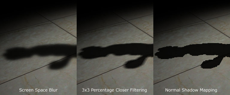
The other topic, which too lend to creating more realistic environments is shadow mapping. As the name implies, shadow mapping creates the appearance of shadows in game. As global illumination, there are many techniques to create them. The basic concept of shadow mapping requires to passes like SSAO, firstly the scene is partially rendered from the perspective of the light source(per light); only objects casting a shadow are rendered. The only thing needed from this pass is the depth. The data of the depth buffer is saved and used as the shadow map for the second pass. In the second pass, the scene is rendered from the perspective of the camera. The depth map from the first pass is then used to compare each pixel with to determine whether the given pixel is in shadow or out of shadow. 

A flaw with this technique is the visual artifacts of jagged shadows can be created due to the limitations of pixels mapping to texels. A simple solution is to blur or anti-alias the shadow. 

An example can be seen here:


Development Progress


Forgive the short length of this update, as my excellent time management skills have led to a drought of time; having to hectic challenge of completing 2 lengthy assignments.

Speaking of which, In animation and production we are to prototype a cutscene rendered in Maya and edited with Adobe Premier. This brings in to the question of how to implement this cut scene into our game. Browsing through the annals of the internet, the methods differ by either having the scene scripted in game and playing it in real time(quite challenging and redundant), or playback a prerendered video.  I am opting for the latter, though we would need to delve deep into Maya.This limits the option of integrating video playback with OpenGl/SFML, or an external library. Another perhaps more interesting option would be to playback the cutscene as a sequence of images on a texture.

Development for our game is advancing along bit by bit. The conversion to modern OpenGl is progressing; the primary concerns of VBOs and shaders are integrated and ready for use.  Transitioning away from old OpenGL perspective and transformations is another matter however… It requires overhauling our previous camera system and math libraries.


Hogue, A. (2014, February 3). Global Illumination [PowerPoint slides].
Retrieved from UOIT College Blackboard site: https://uoit.blackboard.com/

SGHi. (2011). Skyrim - NVIDIA Ambient Occlusion [Screenshot]. Retrieved from http://www.nexusmods.com/skyrim/mods/31/?

Shastry, A, S. (2005). Soft edge shadow comparison [Screenshot]. Retrieved from http://www.gamedev.net/page/resources/_/technical/graphics-programming-and-theory/soft-edged-shadows-r2193


Saturday, February 1, 2014

Blog 2

Before we proceed further, an introduction to our game. It is called Monkey Racers; a racing game situated on a remote volcanic island with a cartoony and vibrant vibe to it. Here is a screen from the game.


As the first month of this freezing semester comes to an end, the workload has gradually increased. What awaits us are two hectic months of development. At the very least the winter Olympics are approaching; too bad I don’t have cable.

This week in INFR2350, we covered post processing effects.

Post processing effects alter the final image. From a graphics point of view this means after all the computations of rendering, lighting, shadows and the like. The outputted 2d image is what would be sent to the screen per frame. Post processing effects are applied to this image to create some very interesting visual appearances; these effects of which are akin to Photoshop’s image manipulation.

To apply these effects, requires mathematical operations to be applied to pixels of the image. Pixels are multiplied with a matrix to create different effects. This matrix takes into consideration the values of adjacent and surrounding pixels to output an altered value for the source pixel. This matrix is called the convolution matrix or kernel/mask or filter.  It is important to note that the values in the matrix are to be normalized to total a value of 1.

GIMP, the free image editor (discount Photoshop) allows for the specification of your own convolution matrix to apply to an image. This makes it a nifty tool to easily see how different filters are applied in OpenGL. Using the screenshot from our game, we take to applying these post processing effects in GIMP.

The simplest of filters which simple blurs the image with a matrix of 1s is the box filter. A smoother blur that produces less artifacts is the Gaussian blur, which does so using Pascal's triangle distribution.


Box Blur
Gaussian Blur


When applied to our screenshot It produces the following image

Blurred


As it is not prominently visible, if we zoom up close we will notice a greater difference
Normal, Box Blur, and Gaussian Blur

Another interesting post processing effect is edge detection. Where given an edges in the image are essentially highlighted to appear as those objects have a sort of glow to them. This can commonly be seen in games to guide players to objects of interest. To achieve this effect Sobel filtering can be used. For optimization purposes, rather then a single pass, two passes of the filter are used; the same can be said of Gaussian blur. One pass for each axis (x,y) are used then merged to create the final image.

Sobel filter for X and Y

 The image produced from applying the 2 filters, notice how the outline of the fences, and monkey are more noticeable.


One of the major effects seen of late that AAA games have that is commonly a challenge for weaker graphics card is HDR Bloom. HDR stands for high dynamic range, which signifies the range of colors available. Under normal imaging standards, there are 256 colors available per pixel, what HDR does is simulate a much larger range. This is done by modern day cameras by taking pictures of different exposure levels to produce a combined image. The combined image is vibrant with a wide palette of colors, often seen as glowing and bright.

The HDR bloom effect is created in graphics by firstly creating a bright version of the scene, applying a blur filter to it, then combining this image with the original.

Highlights

Highlights + several passes of gaussian blur

Final HDR scene with (highlights + blur) + original image

With enough previews of the shader effects to add to the game, the challenge is in now implementing them...


Hogue, A. (2014, January 31). Fullscreen effects PostProcessing [PowerPoint slides].
Retrieved from UOIT College Blackboard site: https://uoit.blackboard.com/


Saturday, January 25, 2014

Blog 1

After much delay, here is my first blog of INFR2350 – Intermediate Graphics.

This entry will cover an overview of material of the past three weeks; namely VBOs, shaders and lighting.

VBO

In modern OpenGL, with shaders, we gain the ability to program directly to the gpu how our data is to be computed. Prior to touching on shaders, we need to know the difference in how to pass our data to begin with. Unlike old opengl where we interate through draws of glVertex, glNormal and glTexCoords, we only need to pass the data once and simple call draw when the object needs to be rendered. To achieve this, there are many ways to pass the data to the gpu  as a VBO, the gist of it is either pass arrays of vertices, normals and texCoords or to organize the data in a single array and pass that instead.

Shaders

Shaders are essentially small programs (like functions) run on the GPU. They are fed a number of inputs, performs calculations and then the output is passed further along the pipeline. What is important to note is that very small iterative pieces are passed one by one, not the entire object itself; for instance the properties of vertex location, normal, and texCoord of a pixel. The changes to the vertex are never returned as this would be both costly and unnecessary. As the vertices are processed individually (in parallel on the gpu), previous results are not to be relied on.

Lighting

Though we covered lighting models in intro to graphics, a brief review is needed to refresh dormant knowledge.

OpenGL uses the Blinn-Phong Lighting model to simulate realistic lighting. Under the Phong model, three color components are calculated and then added together to determine the color (specular, diffuse, and ambient)

Ambient is a global ambience where all light is of the same color, it can be thought of indirect light with no source.
where k is come coefficient for the intensity
L is the color of the light

Diffuse is lighting where color is scattered by the material in accordance to normal of the object

where k is come coefficient (representing material properties such as absorbed, non-reflected light)
l.n is the dot product between the incident ray and the normal,
also the cosine of the angle of normal to l
L is the color of the light

Specular is the shiny reflection of objects and light to viewer

Where k is come coefficient
Cosa  φ is a shininess coefficient  and φ is the angle of viewer and reflected ray
                Also the dot product of the reflected ray and the viewer r.v
L is the color of the light

In the Blinn-Phong model that OpenGl uses, a halfway vector is computed for optimization purposes. Instead of needing to determine the reflected ray, we use the halfway vector of l and v and sub in n.h in place of r.v.


Hogue, A. (2014, January 13). Intro to Shaders [PowerPoint slides].
Retrieved from UOIT College Blackboard site: https://uoit.blackboard.com/

Pazzi, W. R. (2013, December 2). Intro to Computer Graphics Review & Questions [PowerPoint slides]. Retrieved from UOIT College Blackboard site: https://uoit.blackboard.com/