Sunday, February 23, 2014

Blog 5

With study week at an end, the midterm is just a day away. I will dedicate this post as a sort of light review on topics I’ve have not touched on in these blog posts.

It is important to distinguish the differences between modern and old opengl, as such understanding how that the GPU access data through buffers and processes it in parallel; with 1000s of cores vs. the 4 or so cores of the CPU. With shaders, the once fixed pipeline can now be accessed and programmed specifically to our needs; no longer do we have to rely on slow CPU based methods. To fully understand this, we need to understand the graphics pipeline.

Graphics Pipeline

Vertex data is passed though vertex buffer objects that are sent to the GPU. Setting up these VBOs allow us to access them in the vertex shader as input by specifying layout (location=attribute index) in vec3 pos. Other data can be passed via uniform variables. In the vertex shader, a location is passed along by specifying the value to gl_Position. The next stage, after each vertex is processed is the triangle assembly. In the triangle assembly, the vertex locations are used to create basic triangles by connecting groups of 3 vertex and connecting them together – this forms the full object passed into the vbo. In the next stage, the rasterizer goes through each triangle and determines whether to clip portions of it depending on if it visible in screen space. The remaining unclipped portions of the triangle are converted to fragments. If other data is passed along with the location (normal, color, uv) the rasterizer will also interpolate between the vertices of the triangle and assigns each fragments interpolate values of color, normal or uv coords. The last step is to process each fragment in the fragment shader. Here, we can are passed along values from the vertex shader and the fragment itself. In this shader we typically manipulate the color of the fragment to create different effects such as lighting, can sample values from a texture and map them using tex coords. When all is done, the data can be outputted in the same way as layout (location=attribute index) out vec4 color. Data is sent to an FBO where it can be drawn on screen or stored for later use (such as a second pass for post-processing effects).
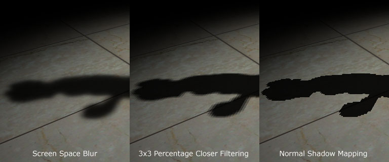
Shadow Mapping

Although I made mention to how shadow mapping works in previous posts, I never went through in enough detail or make mention of the math behind it. After the shadow map is created from the first pass of the light’s perspective, the second pass is that of the screen’s perspective. From here, we need to map pixels from this space to that of the shadow map to compare whether a given pixel is occluded. What we have is the world to light matrix (LTW) and world to camera matrix/modelview (CTW), what we need is to transform a pixel from camera space to light space, so LTW CTW vC . But that doesn’t work as the from and to do not match LTW CTW v, what we need instead is LTW (WTC) vC  . To get (WTC), we need the inverse of the model view matrix CTW-1

Sunday, February 16, 2014

Blog 4

On our lecture on Monday, we had a look into the visual techniques employed in the game Brutal Legend. As the GDC talk was quite lengthy, I will mention what I thought was interesting and could be added to our game.

Brutal Legend has an art style focused towards looking like the cover art of the heavy metal albums of old. This art essentially looks apocalyptic with stormy environments and very dramatic scenery. To create these environments, Brutal Legend uses a lot of particle effects. To light these particle effects appropriately, they use “center-to-vert” normal. Center-to-vert normals have every triangle’s vertex normal facing the direct opposite direction to the center. This creates the illusion that a particle (2d plane with texture) to have a volume; appearing to have depth that is spherical. Using this technique, particles such as smoke, which would almost have a flat billboard like appearance, looks realistic; three-dimensional.


The sky in Brutal Legend is very dynamic, constantly shifting, changing and blending with many factors such as weather, time of day and location. The difference from the conventional method of using sky domes/skyboxes was not used here, instead giant particles emitted far into the distance was used as substitute. Layers of these sky particles were used to create the appearance of a realistic sky (layer for stars, moon, lightning and types of clouds.


In order to match the dramatic sky of the game, Brutal legend took to creating equally dramatic environments. It is interesting to see how sequentially, a dull looking environment is step by step enhanced by adding in the elements of sky, fog, shadows, lights and post-processing effects.


Development Progress 

This was quite a hectic week; a filmmaking and animation assignment due. I toiled away into the night working on the pre-visualization (prototype cutscene) that may ultimately be finalized and integrated in-game. I also took the effort of using textures and actually models rather than just blocked in primitives; as a result, created a scene very close to what we want our finished game to look like.


Other than that, there has been little progress as far as our game goes. Having to upgrade our first level from the dull maze, I needed to implement terrain. As you can see in the video, we have a map all ready for importing into our game; the issue is of course how to do collision with it. Using a height map will work though there is a cave in the map. We could also try to use ray-casting from the character to the terrain. Another option would be to use shaders…

This reading week, I plan to drudge deep into development and not idle; to work on integrating the new map, and doing a few homework questions in the process.


Demoreuille, P., Skillman, D. (2010). Rock Show VFX - The Effects That Bring Brutal Legend to Life. Double Fine Productions. Retrieved from http://gdcvault.com/play/1012551/Rock-Show-VFX-The-Effects

Saturday, February 8, 2014

Blog 3 

This week in INFR2350, we covered global illumination and shadow mapping in our lectures, and color manipulation in tutorials.

Global illumination is a more advanced lighting technique that takes into account the addition of reflected rays. It tries to simulate real-world lighting of having rays of light bounce off surfaces indefinitely. This of course comes with the cost of speed. While there are many varieties of techniques, such as radiosity and ray tracing, screen space ambient occlusion or SSAO is the most suitable for games. (at least until hardware improves further). SSAO is implemented in the pixel shader using the depth buffer to sample the rendered texture(first pass) of the screen. Using the surrounding pixels of a given point, occlusion is computed. Essentially, soft shadows are added to up the realism of the game.

Notice how the objects on the table are almost popping out of the image, almost like they are not actually on the table. 

In this second image, with ambient occlusion, the objects blend in with the shadows and feel consistent as part of the scene.

The other topic, which too lend to creating more realistic environments is shadow mapping. As the name implies, shadow mapping creates the appearance of shadows in game. As global illumination, there are many techniques to create them. The basic concept of shadow mapping requires to passes like SSAO, firstly the scene is partially rendered from the perspective of the light source(per light); only objects casting a shadow are rendered. The only thing needed from this pass is the depth. The data of the depth buffer is saved and used as the shadow map for the second pass. In the second pass, the scene is rendered from the perspective of the camera. The depth map from the first pass is then used to compare each pixel with to determine whether the given pixel is in shadow or out of shadow. 

A flaw with this technique is the visual artifacts of jagged shadows can be created due to the limitations of pixels mapping to texels. A simple solution is to blur or anti-alias the shadow. 

An example can be seen here:


Development Progress


Forgive the short length of this update, as my excellent time management skills have led to a drought of time; having to hectic challenge of completing 2 lengthy assignments.

Speaking of which, In animation and production we are to prototype a cutscene rendered in Maya and edited with Adobe Premier. This brings in to the question of how to implement this cut scene into our game. Browsing through the annals of the internet, the methods differ by either having the scene scripted in game and playing it in real time(quite challenging and redundant), or playback a prerendered video.  I am opting for the latter, though we would need to delve deep into Maya.This limits the option of integrating video playback with OpenGl/SFML, or an external library. Another perhaps more interesting option would be to playback the cutscene as a sequence of images on a texture.

Development for our game is advancing along bit by bit. The conversion to modern OpenGl is progressing; the primary concerns of VBOs and shaders are integrated and ready for use.  Transitioning away from old OpenGL perspective and transformations is another matter however… It requires overhauling our previous camera system and math libraries.


Hogue, A. (2014, February 3). Global Illumination [PowerPoint slides].
Retrieved from UOIT College Blackboard site: https://uoit.blackboard.com/

SGHi. (2011). Skyrim - NVIDIA Ambient Occlusion [Screenshot]. Retrieved from http://www.nexusmods.com/skyrim/mods/31/?

Shastry, A, S. (2005). Soft edge shadow comparison [Screenshot]. Retrieved from http://www.gamedev.net/page/resources/_/technical/graphics-programming-and-theory/soft-edged-shadows-r2193


Saturday, February 1, 2014

Blog 2

Before we proceed further, an introduction to our game. It is called Monkey Racers; a racing game situated on a remote volcanic island with a cartoony and vibrant vibe to it. Here is a screen from the game.


As the first month of this freezing semester comes to an end, the workload has gradually increased. What awaits us are two hectic months of development. At the very least the winter Olympics are approaching; too bad I don’t have cable.

This week in INFR2350, we covered post processing effects.

Post processing effects alter the final image. From a graphics point of view this means after all the computations of rendering, lighting, shadows and the like. The outputted 2d image is what would be sent to the screen per frame. Post processing effects are applied to this image to create some very interesting visual appearances; these effects of which are akin to Photoshop’s image manipulation.

To apply these effects, requires mathematical operations to be applied to pixels of the image. Pixels are multiplied with a matrix to create different effects. This matrix takes into consideration the values of adjacent and surrounding pixels to output an altered value for the source pixel. This matrix is called the convolution matrix or kernel/mask or filter.  It is important to note that the values in the matrix are to be normalized to total a value of 1.

GIMP, the free image editor (discount Photoshop) allows for the specification of your own convolution matrix to apply to an image. This makes it a nifty tool to easily see how different filters are applied in OpenGL. Using the screenshot from our game, we take to applying these post processing effects in GIMP.

The simplest of filters which simple blurs the image with a matrix of 1s is the box filter. A smoother blur that produces less artifacts is the Gaussian blur, which does so using Pascal's triangle distribution.


Box Blur
Gaussian Blur


When applied to our screenshot It produces the following image

Blurred


As it is not prominently visible, if we zoom up close we will notice a greater difference
Normal, Box Blur, and Gaussian Blur

Another interesting post processing effect is edge detection. Where given an edges in the image are essentially highlighted to appear as those objects have a sort of glow to them. This can commonly be seen in games to guide players to objects of interest. To achieve this effect Sobel filtering can be used. For optimization purposes, rather then a single pass, two passes of the filter are used; the same can be said of Gaussian blur. One pass for each axis (x,y) are used then merged to create the final image.

Sobel filter for X and Y

 The image produced from applying the 2 filters, notice how the outline of the fences, and monkey are more noticeable.


One of the major effects seen of late that AAA games have that is commonly a challenge for weaker graphics card is HDR Bloom. HDR stands for high dynamic range, which signifies the range of colors available. Under normal imaging standards, there are 256 colors available per pixel, what HDR does is simulate a much larger range. This is done by modern day cameras by taking pictures of different exposure levels to produce a combined image. The combined image is vibrant with a wide palette of colors, often seen as glowing and bright.

The HDR bloom effect is created in graphics by firstly creating a bright version of the scene, applying a blur filter to it, then combining this image with the original.

Highlights

Highlights + several passes of gaussian blur

Final HDR scene with (highlights + blur) + original image

With enough previews of the shader effects to add to the game, the challenge is in now implementing them...


Hogue, A. (2014, January 31). Fullscreen effects PostProcessing [PowerPoint slides].
Retrieved from UOIT College Blackboard site: https://uoit.blackboard.com/